
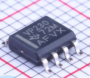
SN65HVD230DR
- Product brand :
- Texas Instruments;Category:

- Manufactory model :
- SN65HVD230DR
- Packaging specifications:
- SOIC-8
- Data Manual :
-
SN65HVD230DR Click to download
- Packaging method :
- tape editing
- Product Consulting :
- Online message QQ:
Product Description
Product Overview The SN65HVD230, SN65HVD231, and SN65HVD232 controller area network (CAN) transceivers are designed for use with 3.3V DSPs or equivalent devices featuring CAN controllers. They are suitable for applications employing the CAN serial communication physical layer compliant with ISO 11898. Each CAN transceiver is designed to provide differential transmit capability to the bus and differential receive capability to the CAN controller at speeds up to 1 Mbps. These devices are specifically engineered for operation in particularly harsh environments, featuring cross-wire protection, loss of ground and overvoltage protection, overtemperature protection, and a wide common-mode range. The transceiver interfaces a single-ended CAN controller with the differential CAN bus in industrial, building automation, and automotive applications. It operates with a common-mode range of -2V to 7V on the bus and can withstand common-mode transients of ±25V. On the SN65HVD230 and SN65HVD231, Pin 8 offers three distinct operating modes: high-speed mode, slope-control mode, and low-power mode. Grounding Pin 8 selects high-speed operation, enabling the transmitter output transistors to switch as fast as possible with no restrictions on rise and fall times. By connecting a resistor to ground on Pin 8, the rise and fall slopes can be adjusted, as the slope is proportional to the output current of this pin. This slope control is achieved through an external resistor value ranging from 10 kΩ (providing a slew rate of 15 V/μs) to 100 kΩ (providing a slew rate of 2 V/μs). If a high logic level is applied to Pin 8, the SN65HVD230 circuit enters a low-current standby mode, during which the driver is disabled while the receiver remains active. This low-current standby mode is exited by the DSP controller when a dominant state (bus differential voltage typically >900 mV) appears on the bus. A unique distinction between the SN65HVD230 and SN65HVD231 is that when a high logic level is applied to Pin 8, both the driver and receiver in the SN65HVD231 are disabled and remain in this sleep mode until a low logic level on Pin 8 reactivates the circuit. On the SN65HVD230 and SN65HVD231, the Vref Pin 5 serves as a VCC/2 voltage reference. The SN65HVD232 is a basic CAN transceiver without additional options; Pins 5 and 8 are no-connect (NC) and remain unconnected.
Application Fields Motor Control Industrial Automation Base Station Control and Status Monitoring Robotics Technology Automotive UPS Control
Product Details
TAG:
Similar products
Prev: No more
Next: SN65HVD234DR